
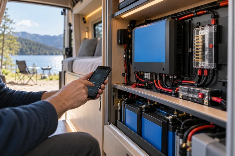
Imagine parking your campervan beside a quiet mountain lake, opening your laptop, and realizing your solar battery is barely charging despite the bright sunshine.
Frustrating, right? You’ve invested in quality solar panels and a decent battery bank, yet something still isn’t working as efficiently as expected. Often, the problem isn’t your equipment. It’s how your solar charge controller is configured.
Advanced MPPT controller configuration for mobile solar systems can make a significant difference in how effectively your setup captures solar energy, charges batteries, and handles changing outdoor conditions.
Unlike stationary solar installations, mobile systems constantly deal with shifting sunlight, partial shading, temperature changes, and limited roof space. These challenges make proper controller settings especially important.
Whether you’re powering a campervan, RV, expedition vehicle, or off-grid trailer, understanding your MPPT controller helps you get more practical value from your existing hardware.
This guide explores everything from solar array sizing and battery charging profiles to temperature compensation, monitoring, and troubleshooting. We’ll keep the technical explanations straightforward while covering the details that matter for reliable off-grid adventures.
1. Understanding How MPPT Controllers Optimize Mobile Solar Power
Before changing advanced settings, it’s helpful to understand what your controller actually does.
MPPT stands for Maximum Power Point Tracking. Essentially, it’s a technology that continuously adjusts the electrical operating point of solar panels to extract as much usable power as conditions allow.
Solar panels don’t produce a fixed amount of power throughout the day. Their voltage and current change according to sunlight intensity, cell temperature, and connected electrical loads.
An MPPT controller responds to these changes automatically.
The Difference Between MPPT and PWM Controllers
Traditional Pulse Width Modulation (PWM) controllers regulate charging by switching the connection between the solar panels and battery.
They’re relatively simple and can work well in smaller systems where panel and battery voltages are appropriately matched.
MPPT controllers take a different approach.
They use DC-to-DC conversion to operate the panels near their maximum power point while delivering suitable charging voltage and current to the battery.
For example, imagine a solar array operating at 36 volts and producing 8 amps.
Its electrical output is approximately:
36 V × 8 A = 288 watts
An MPPT controller can convert much of that available power into a lower voltage and higher current suitable for charging a 12-volt battery.
At an illustrative charging voltage of 14.4 volts and 95% conversion efficiency, the theoretical output would be around 19 amps.
Actual performance depends on equipment efficiency, temperature, battery conditions, and other losses.
Why Mobile Solar Systems Need Smarter Configuration
A rooftop solar installation on a house generally stays in the same position.
A campervan, however, might spend the morning parked beneath trees, travel through cloudy weather, and finish the day facing a completely different direction.
These changing conditions affect solar production.
Modern MPPT technology helps manage fluctuating input, but your controller still needs appropriate voltage limits, battery parameters, and electrical connections.
Think of the controller as the brain of your mobile power system.
The better its settings match your equipment, the more realiable your charging performance becomes.
2. Sizing Your MPPT Controller for the Solar Array
Choosing the correct controller capacity is one of the most important steps in designing an efficient mobile solar installation.
Many people focus exclusively on panel wattage, overlooking other specifications that determine whether the equipment can operate safely together.
A proper configuration starts with understanding solar input voltage, charging current, and battery system voltage.
Calculating Charging Current Requirements
A useful first estimate is to divide your solar array’s rated power by the approximate battery charging voltage.
Suppose your campervan has 400 watts of solar panels connected to a 12-volt LiFePO4 battery system.
If the battery charges at approximately 14.4 volts, the idealized calculation becomes:
400 W ÷ 14.4 V = 27.8 A
This suggests that a 30-amp MPPT controller could be appropriate, provided the manufacturer permits the solar array’s power, voltage, and current characteristics.
This isn’t a complete sizing calculation, though.
The controller must also support the battery voltage and remain within its maximum photovoltaic input specifications.
For example, a Victron SmartSolar MPPT 100/30 supports a maximum PV open-circuit voltage of 100 volts and a maximum battery charging current of 30 amps.
Its published nominal PV power rating for a 12-volt system is 440 watts.
Those are model-specific specifications, not universal limits for every 30-amp controller.
Understanding Input Voltage and Controller Ratings
Three electrical specifications deserve particular attention.
| Specification | Why It Matters |
|---|---|
| Maximum PV Voltage | Determines the highest permitted solar array open-circuit voltage |
| Maximum PV Short-Circuit Current | Limits the solar input current under specified conditions |
| Maximum Charging Current | Limits the current delivered to the battery |
An advanced setup must respect all applicable limits rather than focusing only on output amperage.
Some controllers allow solar-array oversizing and automatically limit output power when sunlight is especially strong.
However, oversizing should only be considered when explicitly permitted by the manufacturer.
Never assume that exceeding maximum PV voltage is acceptable simply because the controller can limit charging current.
These are two completely different limitations.
3. Optimizing Solar Panel Wiring and Array Configuration
Solar panel wiring has a major influence on how effectively your MPPT controller performs.
For mobile applications, the decision usually comes down to connecting panels in series, parallel, or a combination of both.
Each arrangement offers distinct advantages depending on the available roof space, shading conditions, and controller specifications.
Series vs. Parallel Solar Connections
When panels are connected in series, their voltages add together while the string current remains approximately the same.
Imagine two compatible solar panels, each producing 20 volts and 10 amps at maximum power.
Connected in series, their combined operating output would be approximately 40 volts at 10 amps, or 400 watts.
A higher array voltage can help reduce cable current for the same power, potentially lowering wiring losses.
However, series strings can be sensitive to mismatched current production caused by shading or differences between panels.
Parallel connections work differently.
The voltage remains approximately the same, while the currents add together.
Using the same panels, a parallel configuration would produce roughly 20 volts at 20 amps under the same idealized conditions.
Parallel wiring may offer practical benefits when different panels experience uneven sunlight, although performance depends on the panels and their bypass-diode behavior.
The trade-off is higher current, potentially requiring thicker cables and different circuit protection arrangements.
Accounting for Cold-Weather Voltage Changes
Here’s something beginners sometimes miss: solar panel open-circuit voltage generally increases as cell temperature decreases.
That’s important when you’re camping in cold climates.
Suppose two panels each have an open-circuit voltage of 44 volts at standard test conditions, with a voltage temperature coefficient of -0.30% per degree Celsius.
At a cell temperature of -10°C, their estimated combined open-circuit voltage would be approximately 97.2 volts.
That’s already uncomfortably close to the 100-volt limit of a hypothetical controller.
Colder conditions could push the voltage even higher.
Always use the actual panel temperature coefficient, expected minimum cell temperature, and relevant design margins when calculating maximum string voltage.
Also check that operating voltage remains high enough for the controller to start charging during hot conditions.
Good solar array engineering considers both extremes instead of relying only on nominal ratings.
4. Configuring Battery Charging Profiles Correctly
Your battery chemistry has a huge influence on the correct MPPT settings.
A charging profile designed for a flooded lead-acid battery isn’t necessarily suitable for an AGM battery or lithium iron phosphate system.
Using incorrect parameters can reduce battery lifespan, cause poor charging performance, or create unsafe operating conditions.
Understanding Bulk, Absorption, and Float Charging
Many solar controllers use a multistage charging process.
During the bulk stage, the controller supplies available charging current within its configured limits while battery voltage rises.
Once the battery reaches the specified absorption voltage, the controller regulates voltage and charging current typically decreases.
The float stage maintains a lower voltage suitable for the battery’s intended charging strategy.
These stages are especially important for lead-acid batteries.
Lithium batteries can use a somewhat different charging approach, depending on their battery management system and manufacturer specifications.
Some lithium installations use a low float voltage, while others minimize or eliminate sustained float charging.
Setting Up a LiFePO4 Battery Profile
LiFePO4 batteries have become increasingly popular in campervans because they provide useful energy capacity, relatively low weight, and good cycle life.
But they still need compatible charging settings.
For example, Battle Born lists a typical bulk and absorption voltage range of 14.2–14.6 volts for certain 12-volt LiFePO4 batteries.
That doesn’t mean every lithium battery should automatically use those values.
Battery models differ, so the manufacturer’s charging specifications must always take priority.
For advanced configuration, pay attention to absorption voltage, absorption duration, float voltage, maximum charging current, and equalization settings.
Absorption duration shouldn’t simply be extended in an attempt to force more energy into an already charged battery.
And conventional lead-acid equalization charging should not be enabled for LiFePO4 batteries unless the battery manufacturer explicitly specifies a compatible procedure.
Adjusting Charging Parameters for Real Usage
Consider a campervan that uses electricity primarily at night.
Its batteries may begin charging the next morning at a relatively low state of charge.
On another day, the vehicle might remain parked with minimal electrical consumption.
A controller with a compatible adaptive charging algorithm can adjust the absorption stage according to charging conditions.
For systems supporting custom profiles, settings such as maximum absorption time and tail current may provide additional control.
However, these values should be based on the battery manufacturer’s requirements, not random experimentation.
A well-configured system charges effectively without keeping the battery at unnecessarily high voltage.
5. Managing Temperature Compensation and Battery Protection
Temperature can significantly influence charging behavior, especially in vehicles travelling through different climates.
A campervan parked in a hot desert faces very different operating conditions from one spending winter nights in the mountains.
Your controller needs to account for those differences without applying inappropriate corrections.
Temperature Compensation for Lead-Acid Batteries
Lead-acid batteries commonly require charging-voltage adjustment based on battery temperature.
Generally, their recommended charging voltage decreases in warmer conditions and increases in colder conditions.
Many advanced controllers support a configurable temperature compensation coefficient.
For better accuracy, some systems use an external battery temperature sensor.
This is particularly helpful when the charge controller and battery are installed in different locations.
For example, the controller might be located inside a warm electrical cabinet while the battery remains in a cooler storage compartment.
Measuring the actual battery temperature allows more appropriate charging adjustments than relying solely on controller temperature.
Lithium Batteries and Low-Temperature Charging
LiFePO4 batteries require different temperature management.
Most conventional LiFePO4 batteries should not be charged below 0°C unless the battery manufacturer provides a suitable low-temperature charging strategy.
Some products include integrated heaters or battery management systems capable of blocking charging automatically.
Other installations require an external temperature sensor and controller-based charging restrictions.
Be aware that not every MPPT controller can enforce a low-temperature cutoff using its internal sensor.
For example, certain Victron models require compatible external battery temperature information for that function.
Lithium charging profiles also generally disable traditional lead-acid voltage temperature compensation.
Always confirm the exact battery requirements before changing these settings.
Integrating the Battery Management System
The Battery Management System, or BMS, plays a major role in protecting lithium batteries.
Depending on its design, it can monitor cell voltages, temperature, and current while providing protective disconnection functions.
In more advanced mobile installations, compatible communication systems allow the BMS to influence charger operation.
This helps prevent situations where the controller continues attempting to charge a battery that has temporarily disabled charging.
A coordinated BMS and solar controller make life easier when travelling through an unpredictable enviroment.
6. Improving Wiring, Safety, and Installation Efficiency
Even the best controller can’t compensate for poor electrical installation.
Undersized cables, loose terminals, inadequate circuit protection, and excessive heat can all reduce charging performance.
These problems are especially relevant in mobile systems because vibrations and temperature changes create additional stresses.
Reducing Voltage Drop
Voltage drop occurs when electrical resistance causes some voltage to be lost along cables and connections.
For a low-voltage battery system, even relatively small losses can become important.
Imagine your MPPT controller measures 14.4 volts at its battery terminals while the battery itself receives only 14.0 volts during substantial charging current.
That difference may interfere with the intended charging profile.
Cable length, conductor size, connection quality, and current all influence this behavior.
A useful design goal is to minimize unnecessary voltage drop while following the controller manufacturer’s cable recommendations.
Victron’s Wiring Unlimited guide discusses cable selection and recommends aiming for voltage drop below 2.5% in typical calculations.
Sensitive or high-current circuits may justify stricter design targets.
Some advanced systems use remote voltage sensing to compensate for small wiring losses, but this isn’t a substitute for properly sized cables.
Installing Appropriate Protection
A mobile solar system requires more than a basic connection between panels and batteries.
Suitable fuses, circuit breakers, disconnects, cable protection, and grounding arrangements should be selected according to the equipment and applicable electrical requirements.
Battery-side overcurrent protection is particularly important because batteries can deliver extremely high fault currents.
Protective devices must have suitable voltage, current, and fault-interruption ratings.
Install the controller in a location that provides the ventilation clearance required by its manufacturer.
Avoid placing it against insulation or inside a tightly sealed compartment that traps heat.
Routing cables neatly also reduces mechanical stress and makes future inspection more convinient.
Following the Correct Connection Sequence
Many MPPT controllers require the battery connection to be established before connecting the solar array.
This allows the device to detect or establish the appropriate battery system voltage.
For shutdown, some manufacturers specify disconnecting the PV supply before disconnecting the battery.
However, connection procedures vary by model.
Always follow the exact manual rather than assuming every charge controller uses the same startup and shutdown sequence.
Solar panels can generate hazardous DC voltage whenever illuminated, and disconnecting DC circuits under load can create dangerous arcs.
If you’re unfamiliar with safe DC installation procedures, a qualified installer should handle the high-risk work.
7. Monitoring, Troubleshooting, and Fine-Tuning Solar Performance
Installing an MPPT controller is only the beginning.
The real advantage of a configurable system comes from observing its performance and making informed adjustments over time.
Modern controllers with Bluetooth, network communication, or dedicated displays make this process much easier.
Tracking Useful Performance Data
Start by monitoring solar input power, battery voltage, charging current, and daily energy production.
These readings help reveal whether your system is performing as expected.
For example, a 400-watt solar array won’t necessarily deliver 400 watts continuously during a sunny afternoon.
Panel temperature, installation angle, shading, wiring losses, and battery charging demand all affect output.
When the battery is nearly full, the controller may deliberately reduce charging power.
That’s normal behavior rather than evidence of a faulty solar panel.
Comparing daily energy production is often more informative than focusing on one instantaneous power reading.
You can also estimate daily energy availability using a basic calculation:
Daily Solar Energy = Panel Wattage × Peak Sun Hours × System Efficiency Factor
Suppose your installation has 400 watts of panels, receives three equivalent peak-sun hours, and achieves an assumed overall efficiency factor of 75%.
The estimated harvest would be:
400 W × 3 h × 0.75 = 900 Wh
That’s an illustrative estimate, not a guaranteed daily output.
Actual results depend heavily on location, season, parking orientation, weather, and system conditions.
Troubleshooting Common Charging Problems
If your solar controller isn’t charging, begin by reviewing the displayed operating state and any error messages.
Low solar input voltage is one possible explanation.
Some Victron MPPT models require PV voltage to exceed battery voltage by approximately 5 volts to begin charging, with a smaller voltage difference needed to continue operation.
Other controller models may have different startup requirements.
Another common issue is an incorrect battery charging profile.
If absorption or float voltages are set too low, the controller may reduce charging before the battery reaches its intended state of charge.
A BMS restriction, high equipment temperature, or inadequate solar irradiance can also explain unexpectedly low output.
Use the manufacturer’s diagnostics before making adjustments.
Avoid probing energized PV conductors unless you’re qualified to work safely with the voltages involved.
Making Seasonal Adjustments Without Overcomplicating Things
Not every environmental change requires a manual controller adjustment.
In fact, correctly configured automatic algorithms should handle many normal variations.
Instead, focus on observing patterns.
If your panels regularly experience morning shade, consider whether their arrangement could be improved.
If daily solar production consistently falls short of consumption, review your energy budget before attempting to modify charging limits.
Cleaning panels, improving parking orientation, and reducing unnecessary loads may offer better results than changing advanced settings.
Periodically inspect accessible cables, ventilation openings, and mounting hardware according to the manufacturer’s maintenence guidance.
Keep a record of successful controller settings so you can restore them if equipment is replaced or reset.
A smart setup should become easier to operate over time, not more complicated.
Advanced MPPT controller configuration for mobile solar systems is about getting the right balance between energy efficiency, battery protection, and dependable everyday performance.
By correctly sizing your controller, optimizing panel connections, selecting compatible charging profiles, and managing temperature conditions, you can build a more effective off-grid electrical system.
Proper wiring, suitable protective devices, and consistent performance monitoring are equally important for long-term reliability.
Remember that the best settings aren’t necessarily the most aggressive ones. They’re the settings that match your specific solar panels, battery chemistry, controller limits, and travel conditions.
Whether you’re upgrading an existing campervan or building a new solar-powered adventure vehicle, thoughtful configuration makes a meaningful difference.
Ready to improve your mobile solar setup? Review your equipment specifications, document your current settings, and start optimizing your system for safer, smarter adventures.
